9. März 2026
ILS, Follow the Localizer
 How to construct a controller that automatically aligns an airplane with the runway using the deviation from the localizer beam of the Instrument Landing System (ILS) in GeoFS, the browser-based flight simulator?
This article is part of a series on my curiosity-led journey through flight simulation, modeling, navigation & mapping, aviation, control theory, software engineering, and more.
Push a button and make the airplane automatically align itself horizontally with the runway on approach? That is what autopilot can already do in commercial jets in the real world. In GeoFS, the simulator, can we build such an autopilot to fly the Boeing 737-700 down the extended runway centerline and arrive at the runway threshold?
A runway on an international airport is typically 45 meters wide. While that may sound wide, it is a pretty narrow strip when viewed from a distance. Unlike cars, an airplane can’t stop (and then parallel park). Instead, the plane comes in for landing at high speed. Little surprise that it must be kept aligned with the runway for a safe landing. How do pilots manage?
To aid pilots with aligning the airplane, larger airports are typically equipped with an Instrument Landing System (ILS; see SKYbrary or Wiki). In summary, the ILS sends out two directional radio signals. There are good explanations of ILS on the Internet, I will not and cannot provide a better one here. Suffice to say that a localizer placed at the end of the runway emits a signal which the aircraft can use to compute the lateral deviation (angle), and a glide slope station emits another signal which lets the aircraft compute the vertical deviation from the ideal glide slope (typically three degrees).
In this article, we will focus on the lateral deviation only (denoted \(\delta\)): how can we write a computer program steer the airplane in the simulation such that it has zero lateral deviation (\(\delta = 0\)), that is, neatly centered on the extended runway centerline?
Let’s illustrate the problem. Let’s look at the world from above. On the left, you see localizer (\(\textrm{L}\)) and runway threshold (\(\textrm{R}\)) on the runway’s extended centerline (\(\overline{\textrm{LR}}\)). On the right you have the aircraft (\(\textrm{B}\)), and its orthogonal projection onto the centerline (\(\textrm{C}\)). There are two issues our autopilot needs to solve. First, the airplane is not on the centerline: in other words, the cross-track distance is non-zero (\(a = \textrm{BC} \neq 0\)). Second, the aircraft might be pointing into the wrong direction. How do we go about solving these two issues?
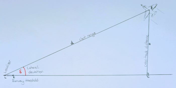
What are the known quantities? The localizer from the ILS provides the autopilot with the lateral deviation \(\delta\) at all times. Assume, additionally, that the autopilot is given the slant range distance \(d\), either from a signal from the ground (look up DME). From these two quantities, we want the autopilot to ultimately compute a control output \(u\) for the control surfaces. For instance, the autopilot may instruct the airplane to roll to one side. How to implement the controller?
Nested controllers are one option. The outer controller takes care of the bigger picture, by computing a (setpoint) heading \(\theta\) at any given point in time. The inner controller is responsible for control the ailerons such to roll the airplane in such a way that it follows the desired setpoint heading. I chose this option because I had good experience when tinkering with other controllers in the past. Anyhow, there are two steps: figure out the heading, then make the airplane turn towards that heading.
The idea? Imagine that you sit in the cockpit. Look out of the cockpit window. Imagine the runway centerline painted on the earth with a big spray can. Choose a lookahead point on the line, at a fixed distance ahead of the airplane. Imagine that you were able to instantly turn the airplane towards that lookahead point. That is the setpoint heading. What happens then, over time? Well, the airplane does not instantly turn, of course. Thus it will not actually reach the centerline at this point. Instead, it will “chase the lookahead point” without ever reaching it, getting closer to the centerline in the process, bringing the setpoint heading closer and closer to the runway heading. That is the idea (which I did not come up with; I think it is called a “pure pursuit controller”). How to implement it? Three steps. Do the maths. Write some unit tests. Implement the autopilot.
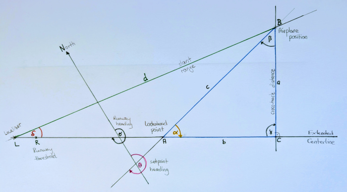
The maths first. We’re looking at a small area only, as the range of ILS is limited anyways. No need for spherical trigonometry. Planar trigonometry will more than suffice. North is north. Keep it simple. Known quantities:
$$ \begin{aligned} & d & \textrm{slant range} \\ & \delta & \textrm{lateral deviation} \\ & \sigma & \textrm{runway heading} \\ & b & \textrm{lookahead distance} \\ \end{aligned} $$Recall, what we want to compute is:
$$ \begin{aligned} & \theta & \textrm{setpoint heading} \\ \end{aligned} $$While we are on a roll, more definitions (and to recap):
$$ \begin{aligned} & \textrm{L} & \textrm{localizer} \\ & \textrm{A} & \textrm{lookahead point} \\ & \textrm{B} & \textrm{airplane position} \\ & \textrm{C} & \textrm{centerline projection} \\ & \triangle \textrm{ABC} & \textrm{triangle} \\ & \alpha,\beta,\gamma & \textrm{angles in right triangle} \\ & a,b,c & \textrm{sides in right triangle} \\ \end{aligned} $$Our focus is on the “lookahead triangle” \(\triangle \textrm{ABC}\). We want to determine the angle \(\alpha\) in \(\triangle \textrm{ABC}\), aiming at the lookahead point. We can compute the (absolute) setpoint heading \(\theta = \sigma-\alpha\). If the runway were pointing north (\(\sigma = 0\)), then the setpoint heading would be \(\theta = -\alpha\). Fancy greek letters, but we are really just determining the angles in \(\triangle \textrm{ABC}\). Right off the trigonometry shelf:
$$ \tan \alpha = \frac{a}{b} \\ $$and thus
$$ \alpha = \arctan{\frac{a}{b}} $$In other words, we can compute the heading from cross-track distance \(a\) and the lookahead distance \(b\).
The lookahead distance \(b\) is a parameter we can choose. Intuitively, the smaller the lookahead distance, the more aggressive the controller will try to reach the centerline as fast as possible (and possibly overshoot). We will look at this again later.
The (signed) cross-track distance is \(a = d \sin \delta \), at least on a flat piece of paper. Putting it together:
$$ \theta = \sigma - \arctan \frac{d \sin \delta}{b} $$Whenever I see a formula, I get suspicious. Particularly, when I derived it myself. It must be full of bugs! What is the antidote to bugs? Tests. We can ask ourselves: what happens in the limits? For example, what happens if the lateral deviation is zero (\(\delta\to0\))? Well, the setpoint heading is equal to the runway heading: perfectly aligned.
$$ \theta = \sigma - \arctan \frac{d \sin 0}{b} = \sigma - \arctan 0 = \sigma $$What happens if the aircraft is really far away from the centerline? Yes, it is unrealistic, the Earth is finite, and definitely not flat. But what happens in our flat paper model world when the cross-track distance grows (\( a\to\infty\))?
$$ \lim_{a\to\infty} \theta = \sigma - \lim_{a\to\infty} \arctan \frac{a}{b} = \sigma - 90 \degree $$We can also get an idea how the cross-track distance affects how the controller selects a heading. What happens if we choose not to look ahead at all, that is \(b \to 0\) with \(a > 0\)? The controller thinks that it is always best to turn orthogonally towards the centerline, even when the airplane is already close to it. Not a good choice.
$$ \lim_{b\to\infty} \theta = \sigma - \lim_{b\to\infty} \arctan \frac{a}{b} = \sigma - 90 \degree $$What about a large lookahead distance? The plane might never get closer to the runway centerline. Not a good choice.
$$ \lim_{b\to\infty} \theta = \sigma - \lim_{b\to\infty} \arctan \frac{a}{b} = \sigma $$Are there bugs in the formula for the setpoint heading? So far we have not found any. Time to put it into practice.
The inner control loop uses the error between current heading of the aircraft and the setpoint heading \( \theta \), and controls the roll angle (via ailerons) accordingly. I’ll save the details for another day. In broad terms, however, the inner control loop applies a sinusoidal curve to smoothly determine the roll angle of the airplane up to maximum (30 degrees), and then uses a PID controller to decide on the lateral input. A yaw damper, also PID-based, corrects for induced yaw during turns. A story for another day.
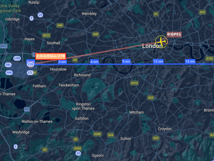
Time to put it into practice. I set up an experiment in GeoFS. Place the Boeing 737-700 off the extended centerline of runway 27R at London Heathrow, roughly at St. Paul’s Cathedral (too far north on the approach). The runway heading is approximately \(\sigma \approx 270 \degree \), the runway heading encoded in the name of the runway.
To my big surprise, it worked straight away! The controller initiates an S-shaped turn, and rolls the airplane towards the extended centerline. At first, it steers fairly directly towards the line. As the plane approaches the line, the angle between lookahead point and localizer diminishes. The plane then flies over Kew Gardens, and soon after, approaches 27R in near perfect alignment.
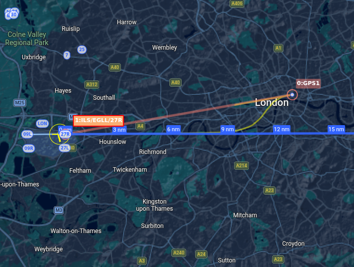
The airplane started over St’Paul’s Cathedral (“GPS1”). The red line (not relevant here) connects this waypoint with the threshold of runway 27R. The yellow line is the path that the airplane flew in the simulator, with the controller employing the \(\triangle \textrm{ABC}\) “lookahead” method.
The airplane does not follow the glide slope. That’s because the controller only manages the lateral deviation, aligning the plane with the runway. We can see the perfect alignment of the airplane with the runway centerline from the belly cam of the Boeing 737-700 in the GeoFS simulator.
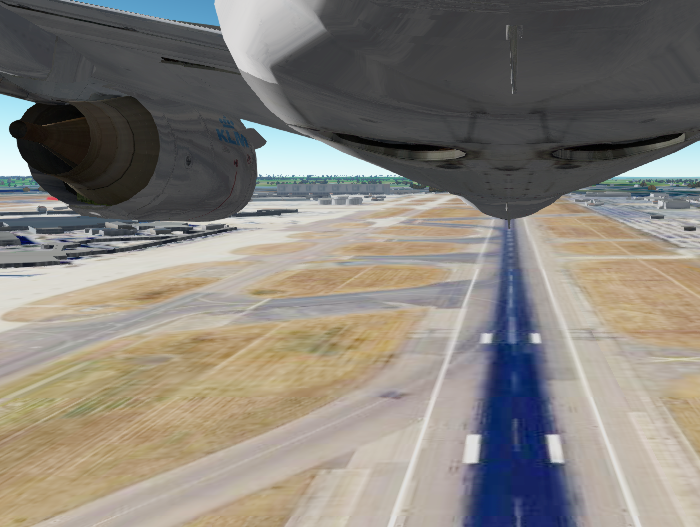
The belly cam shows how the autopilot neatly aligned the airplane with the centerline of runway 27R.