12. März 2026
ILS, Follow the Glide Slope
 How to build a controller that automatically puts an airplane on the glide slope from the beam of the Instrument Landing System (ILS) in GeoFS, the flight simulator?
This article is part of a series on my curiosity-led journey through flight simulation, modeling, navigation & mapping, aviation, control theory, software engineering, and more.
Previously, I allowed myself to nerd out a little bit on building a pursuit controller for aligning the airplane with the runway based on the localizer beam emitted by the ILS, as simulated in GeoFS. For context, GeoFS is a browser-based flight simulator. With a little creativity, it’s possible to program extensions. So why not program a button that makes the airplane capture the ILS beam, find and stay on the perfect glide slope until it almost magically arrives at the runway threshold, without any hands on the controls?
Three degrees. That is the typical angle at which an airplane approaches the runway before landing. It’s a tricky business. Can’t be too high. Can’t be too low. Can’t be too fast. Can’t be too slow. Kinetic energy plus potential energy. Keep enough energy. Not too much. How tricky? I don’t know. I am only playing occasionally with the flight simulator. I can say that it does not feel easy. How tricky to program a computer to steer the plane to the runway on the ideal glide slope? Let’s find out.
Runways at major aiports are likely to be equipped with an Instrument Landing System (ILS). See SKYbrary for details. The ILS sends out a radio signal that lets the airplane compute its deviation \(\delta\) from the ideal glide slope \(\sigma\).
How to use the deviation in order to control the rate of descent of the simulated airplane such that it stays on the glide slope? Let us illustrate the problem. Let’s assume that the airplane is \(\delta=1\degree\) above the ideal glide slope \(\sigma=3\degree\).
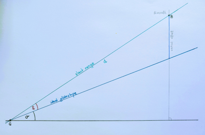
Somewhere along the approach to the runway, the airplane needs to attain the ideal glide slope and keep it. A plane has momentum and can’t just lose its altitude in an instant—it needs to do so gradually. A vertical offset from the ideal glide slope needs to be reduced over time. The idea?
We pick a lookahead point, at a certain distance ahead from the airplane. We imagine there is a beam rising from the ILS station. Aim at having the airplane reach that beam just at that lookahead point. Then follow that beam down to the runway. In other words, let’s build a “pursuit controller” that chases the lookahead point. Just like when following the localizer. How to build it?
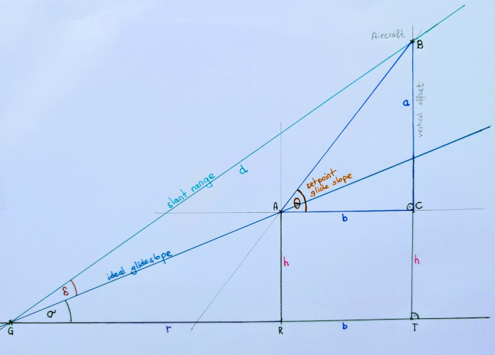
First, the maths. I struggled a bit, my trigonometry skills fairly rusty. After a few attempts, I found one way to compute the setpoint glide slope \(\theta\) from slant rage \(d\), deviation \(\delta\) and lookahead distance \(b\) in such a way that the setpoint glide slope makes the airplane converge onto the ideal glide slope \(\sigma\).
In our example where the airplane is one degree above the glide slope, we need to initially have a setpoint glide slope \(\theta\) with \(\theta < \sigma\) in order to gradually correct for deviation \(\delta\). In other words, make the airplane descend more steeply than the ideal glide slope until the latter is attained.
$$ \begin{aligned} & d & \textrm{slant range} \\ & \delta & \textrm{vertical deviation} \\ & \sigma & \textrm{ideal glide slope} \\ & b & \textrm{lookahead distance} \\ \end{aligned} $$What we want to compute is:
$$ \begin{aligned} & \theta & \textrm{setpoint glide slope} \\ \end{aligned} $$Labeling all the things:
$$ \begin{aligned} & \textrm{G} & \textrm{glide slope station} \\ & \textrm{A} & \textrm{lookahead point} \\ & \textrm{B} & \textrm{airplane position} \\ & \textrm{C} & \textrm{right angle vertex} \\ & \triangle \textrm{ABC} & \textrm{lookahead triangle} \\ & \textrm{R} & \textrm{projected lookahead point} \\ & \textrm{T} & \textrm{projected aircraft} \\ & \textrm{r} & \overline{\textrm{GR}} \\ & \textrm{a} & \overline{\textrm{BC}} \\ & \textrm{b} & \overline{\textrm{AC}}, \overline{\textrm{RT}} \\ & \textrm{h} & \overline{\textrm{AR}}, \overline{\textrm{CT}} \\ \end{aligned} $$The angle at \(\textrm{A}\) in \(\triangle \textrm{ABC}\) is the setpoint glide slope \(\theta\). That’s what we are looking for. How do we compute this angle? There are likely simpler approaches: I am simply presenting the first one I found after several attempts.
(1) From lookahead \(\triangle \textrm{ABC}\), we get
$$\tan \theta = \frac{a}{b}$$(2) \(\triangle \textrm{GAR}\) tells us
$$\tan \sigma = \frac{h}{r}$$(3) Looking at right \(\triangle \textrm{GBT}\) formed by emitter and aircraft, we get
$$r + b = d \cos (\sigma + \delta)$$(4) From \(\triangle \textrm{GBT}\), obtain
$$\tan(\sigma+\delta) = \frac{a+h}{r+b}$$The three triangles allow us to put the current glide slope, the ideal glide slope, and the setpoint glide slope in relation: each triangle contains one of the angles of interest.
You may object about my variable naming: sorry! You may object to how I assigned signs to each angle: as long as they are consistent, things should work regardless.
Now use (1-4) to eliminate \(a\), \(h\) and \(r\)
$$\begin{aligned} b\tan\theta &= (r+b)\tan(\sigma+\delta)-h \\ &= (r+b)\tan(\sigma+\delta)-r\tan\sigma \\ &= d\cos(\sigma+\delta)\tan(\sigma+\delta)-(d\cos(\sigma+\delta)-b)\tan\sigma \\ &= d\cos(\sigma+\delta)\tan(\sigma+\delta)-d\cos(\sigma+\delta)\tan\sigma+b\tan\sigma \\ &= d\cos(\sigma+\delta)(\tan(\sigma+\delta)-\tan\sigma)+b\tan\sigma \\ \end{aligned} $$Dividing by \(b\), and inverting the tangent finally yields
$$\begin{aligned} \theta=\arctan\{\frac{d}{b}\cos(\sigma+\delta)(\tan(\sigma+\delta)-\tan\sigma)+\tan\sigma\} \end{aligned} $$Hooray. But is it any good?
Let’s check what happens if the airplane is sitting perfectly on the glide slope already (\(\delta=0\)). In this case, the first term of the \(\arctan\) argument cancel out, and we can see that \(\theta=\sigma\) in this case. Good. After all, we require that the airplane is kept on the glide slope once having reached it.
What happens if we choose different lookahead distances? First, let’s look at the extreme, and choose a lookahead distance infinitely far ahead, with some quality binoculars. We can see that the controller chooses a setpoint glide slope equal to the ideal glide slope. Which only works if the airplane is already on the glide slope, and a poor choice otherwise.
$$ \lim_{b\to\infty} \theta = \arctan(0 + \tan\theta) = \theta $$What happens if we choose an extremely small lookahead distance, and the airplane is offset from the ideal glide slope (\(\delta>0, \sigma>0\))? Somewhat informally, we will see that the setpoint glide slope will be set to nearly \(90\degree\), suggesting free fall, essentially. Not a good choice.
$$ \lim_{b\to0} \theta = "\arctan(\infty)" = \frac{\pi}{2} = 90\degree $$We can smell potential trouble now. What if the airplane is far away still? With small lookahead distance \(b\), we can see that the suggested setpoint glide slope can become steep. This becomes evident either by looking at the visualization, or by looking at the limit of \(d\to\infty\).
However, we can fix this probably fairly easily through a range of mechanisms: by clipping the setpoint glide slope, for instance. We could also divide the approach into two time frames. In the first time frame, the localizer is captured, but the glide slope is not: fly the airplane level and intercept the glide slope from below (the latter is the standard way of capturing the glide slope, as far as I understand). In the second time frame, deviations never become too large because the airplane is already close to the ideal glide slope. Anyhow, this might be better answered through experimentation in the simulator.
Many more questions come to my mind. Like, can’t we choose another function that makes the setpoint glide slope \(\theta\) slowly converge to the ideal glide slope \(\sigma\)? Likely yes. What I like about the formulation with the lookahead triangle is that it is easy to interpret geometrically.
Are we there yet? Not quite. So far, we have calculated the glide slope \(\theta\) that the airplane should settle on at any given point in time. The controller still needs to actually make the airplane sink at the appropriate rate by adjusting the flight controls.
For that, I picked a nested control loop. The outer loop computes glide slope \(\theta\), which is changing slowly. The inner loop implements a PID controller that deflects the elevator until the aircraft attains the setpoint vertical speed corresponding to the setpoint glide slope \(\theta\). We can calculate the setpoint vertical speed using \(\sin\theta\) and the ground speed (matching indicated airspeed if there is no wind).
In combination with this nested loop that controls vertical speed on elevators, we must also achieve that the airplane must have sufficient energy to stay on the setpoint glide slope, and that the airplane doesn’t speed up and arrive at the runway with too much energy at high speed. How to do that? Autothrottle: I set up an independent PID controller which slowly adjusts the throttle for controlling the airspeed.
Power and pitch affect both airspeed and altitude. If both controllers—speed on thrust, vertical speed on elevator—act in a “short-sighted, panicky” manner, it is easy to have them fight over airspeed and altitude, leading to oscillations. I have seen this in the simulator when using naive PID control to control the vertical speed on the elevator without any lookahead. In contrast, the pursuit controller we built doesn’t understand any flight dynamics, but does a certain amount of planning nevertheless.
Time to put the autopilot to the test. I put the Boeing 737-700 above St. Paul’s Cathedral in London, too far north of the approach to 27R at London Heathrow, and a thousand feet above the ideal glide slope—ignoring the peril of intercepting glide slope from above. No hands on the controls. Autothrottle manages airspeed by adjusting the throttle. The pursuit controller developed in ILS, Follow the Localizer aligns the airplane laterally with the runway using the ailerons in collaboration with the yaw damper controlling the rudder for coordinated turns. Finally, the glide slope controller continously actuates the smoothly changing setpoint glide slope in order to make the airplane settle on the ideal glide slope.
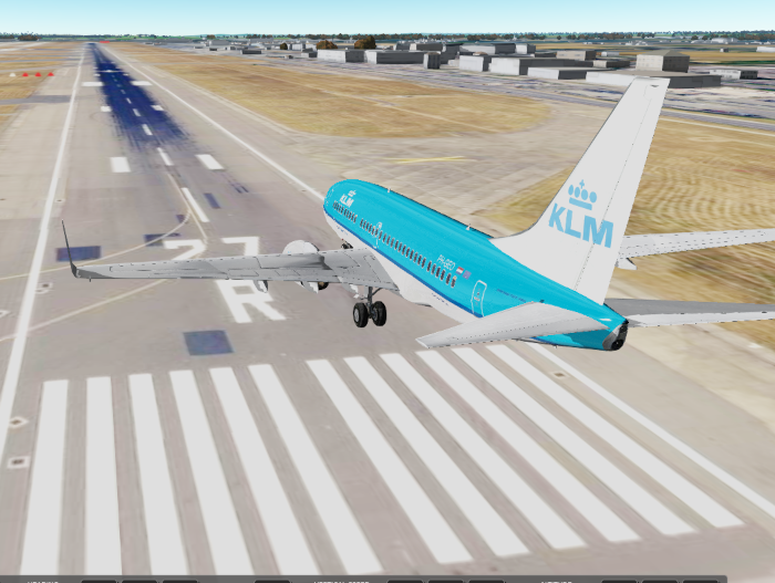
No hands on the controls. The autopilot flies the airplane all the way from St. Paul’s Cathedral at 5000 feet (too far north, too high), while the autothrottle kept the airspeed under control. The airplane arrives with good alignment, and at a decent altitude above the runway threshold.
Can the airplane automatically land in the simulator? The combination of autothrottle, localizer following, glide slope following sets a solid base. What is missing is to precisely control airspeed and vertical speed on the final approach over the runway through a controlled flare. I have read that real aircraft no longer use ILS for the last meters, but rather rely on the radar altimeter to read the altitude above ground level, and then initiate the flare at the right time, in the right does. Exciting challenge.