9. April 2026
Autoland
 How to build a controller that automatically lands an airplane after approaching a runway via the Instrument Landing System (ILS) in GeoFS, the flight simulator?
This article is part of a series on my curiosity-led journey through flight simulation, modeling, navigation & mapping, aviation, control theory, software engineering, and more.
Previously, I described how to write a program that steers an airplane to the runway threshold while following the glide slope prescribed by the Instrument Landing System (ILS).
This would bring the airplane align with the runway centerline, and fly a stable approach, but still required me to take over the controls on final. What about automating that part as well? How to automate it?
The straightforward idea: determine the moment for initiating the flare and reduce vertical speed, automatically deploy spoilers and brakes upon ground contact, then steer the airplane with the rudder to keep it on centerline.
I lack a bit of knowledge on what information would be available to a real aircaft. But I figured that I can assume the airplane to have a precise enough radio altimeter; assume the airplane capable of sensing ground contact; assume the localizer beam to be available on the ground after the touchdown.
The flare is initiated at 35 feet above the ground—determined through trial and error with the Boeing 737-700. I hardcoded 60 feet/min as the targeted vertical speed at touchdown—also determined through trial and error. A PID controller then executes the flare based on the error between current vertical speed and targeted vertical speed. This controller gradually decreases vertical speed from initially approximately 700 feet/min down to the 60 feet/min.
Once the sensors detect ground contact, the spoilers are deploy automatically, and the brakes engage. The lateral mode of the autopilot uses the same kind of pursuit controller when on ground as when finding and following the localizer beam during the approach. However, only the rudder is used to control the airplane: the ailerons do not have any authority once on ground. The simulator models this correctly.
How well did it work? On the first few rounds of testing, beautifully. Later attempts, not so much. But one thing at a time. I sent the plane to runway 27R at London Heathrow to test the new autoland procedure. Whoosh. Over Kew Gardens. Across the Thames. So far, so good. The plane reaches the runway threshold, lands a bit short of the markings of the touchdown zone, rollsout with slight corrections. That’s about how it went after the parameters were tuned.
To make things harder, I added a mild crosswind component of a few knots. Alas, that was already enough to make the plane never align with the runway centerline. Why? The crosswind acts as a force on the airplane, perpendicular to the runway centerline. We can also think of the pursuit controller specifying a force with which the airplane is pulled towards the runway centerline. When those two forces are in equilibrium somewhat offset from the runway centerline, the airplane will follow a parallel to the runway centerline. Lateral drift. That is not what we want. How to fix it?
My first attempt was unsuccessful. The pursuit controller acts a bit like a P-controller without memory, without an integral part to keep track of whether the deviation from the runway centerline is ever actually reducing. Why not make it act more like a PI controller, with an integral part? However, adding an integral part helped a bit, but not enough. At the same time, it induced oscillations. I clamped the values to avoid integral windup, a known issue with PID controller. I played around with the integral gain, but to no avail.
The second attempt was more fruitful. The idea is based, again, on observing how you can fly the airplane manually to the runway in presence of crosswind. You can do this by approaching the runway in a so-called “crab”, effectively compensating for the lateral drift by moving the nose of the aircraft somewhat into the wind. Can we programmatically achieve the same thing? The question then becomes: how much to move the nose into the wind at any given point in time? How to compute this “compensation angle”?
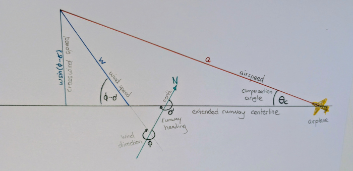
This sketch shows the compensation angle (also called “Wind Correction Angle” or “crab angle” as I have learnt later) and its relation to the extended runway centerline, the wind direction, the wind speed, and the airspeed.
A few definitions. They will make sense later.
$$ \begin{aligned} & \theta_c & \textrm{compensation angle} \\ & \sigma & \textrm{runway heading} \\ & \phi & \textrm{wind direction} \\ & w & \textrm{wind speed} \\ & a & \textrm{airspeed} \\ \end{aligned} $$Let us build some intuition first. When there is no crosswind, no need to compensate: we want \(\theta_c = 0\). If there is a little crosswind compared to airspeed, only compensate a little: \(\theta_c = 0\) needs to be small. Conversely, in an extreme case, if the speed of the crosswind were to exceed the airspeed, the airplane would have negative groundspeed: impossible to compensate. In more realistic cases, the compensation angle needs to be a few degrees. But how many, concretely?
First, we calculate the crosswind speed given the runway heading, wind direction, and wind speed. Given the right triangle formed by aircraft, wind direction, and extended runway centerline, we can calculate the crosswind speed: \(w\sin(\omega – \sigma)\).
Second, let’s assume the airplane is aligned on the runway centerline, but points away at an angle of \(\theta_c\). During one unit of time—say, a second—the airplane will travel at the compensation angle \(\theta_c\) away from the runway centerline, slowed down by any headwind component of the prevalent wind. However, there is also crosswind. That crosswind makes the airplane drift back towards the centerline. Assume the airplane travels over the ground towards the centerline at a speed equal to the crosswind, that is \(w\sin(\omega – \sigma)\). We need to choose \(\theta_c\) such to strike the perfect balance.
Another right triangle illustrates how to find this balance. The opposite site of angle \(\theta_c\) represents the crosswind speed \(w\sin(\omega – \sigma)\). The hypotenuse of the triangle represents the airspeed \(a\). In one unit of time, we can equivalently think of the sites of the triangle as distances. Taking the formula for the sine:
$$\begin{aligned} \sin(\theta_c)=\frac{w\sin(\phi - \sigma)}{a} \end{aligned} $$Rearranging things a little bit, and we obtain the desired compensation angle \(\theta_c\):
$$\begin{aligned} \theta_c=\arcsin\{\frac{w}{a}\sin(\phi - \sigma)\} \end{aligned} $$Let me be clear here. This is a construction for a controller. Not a rigorous derivation based on the laws of physics. Rather, the compensation angle is based on the intuition built previously (and some basic trigonometry embellished with beautifully typeset greek letters, what’s not to love).
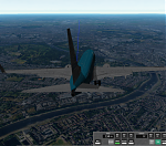
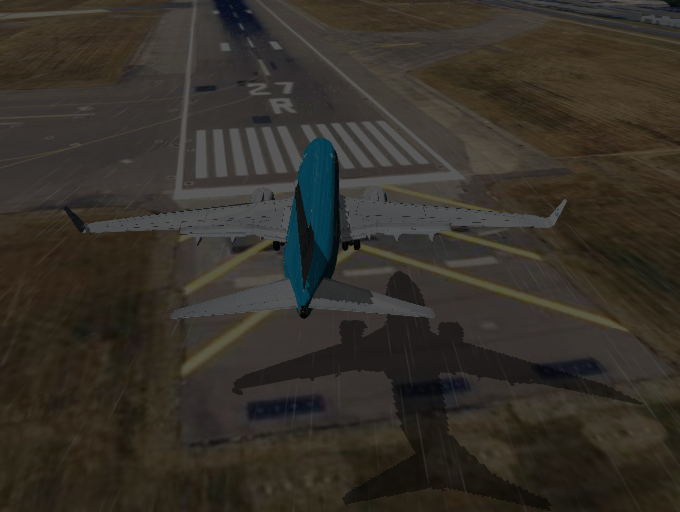
The autopilot is flying a crabbed approach. The airplane is flying towards runway 27R, but it is pointing its nose towards the wind (25 knots from 347 degrees). I painted the extended runway centerline in blue.
Before looking closer on how things fare in the simulator, let’s run few checks on whether the compensate angle acts the way we want it to. When there is no wind (\(w=0\)), no need to compensate (\(\theta_c = 0\)); true as the arcsine is zero for argument zero. Good. When there is pure headwind or pure tailwind, \(\sin(\phi – \sigma)\) is zero, thus \(\theta_c = 0\). Good. When the airspeed is high, the compensation is small: consider \(\lim_{a\to\infty} \theta_c = 0\). Good. When the wind direction is perpendicular to the runway (\(\phi – \sigma = 90^\circ \)), the sine reaches its maximum. Good. We need \(w \leq a\) for because the arcsine only takes values between -1 and 1; this makes sense, can’t go flying when the crosswind is that bad. Matches expectations.
In the code, this piece computes the heading for the autopilot to fly. The heading setpoint the sum of the heading computed from the localizer beam alone (see ILS, Follow the Localizer) and the crosswind compensation angle. Both localizer beam and crosswind compensation affect the chosen heading.
    this.observeILSGuidance.execute((ilsGuidance: ILSGuidance) => {
      const wind = this.getWind.execute()
      headingSetpoint =
        localizerHeadingSetpoint({
          runwayHeading: ilsGuidance.getHeading(),
          localizerDistance: ilsGuidance.getDistance(),
          localizerDeviation: -ilsGuidance.getHorizontalDeviation(),
          lookaheadDistance: 1.0,
          geo: this.geo,
        }) +
        crosswindCompensation({
          runwayHeading: ilsGuidance.getHeading(),
          windDirection: wind.getDirection(),
          windSpeed: wind.getSpeed(),
          airspeed: this.aircraftRepo.getAircraftPerformance().getAirspeed(),
          geo: this.geo,
        })
      lateralDeviationMeter.record(ilsGuidance.getHorizontalDeviation())
    })
Time to put it to the test in the simulator. Let the Boeing 737-700 under bad weather conditions approach runway 27 at Heathrow. I tested various conditions so far. Without the compensation, a few knots were enough to push the airplane off the intended track in the simulator. With the compensation, the jet now gracefully handles crosswinds of >20 knots. No oscillations. Just small and smooth corrections. Amazing.
However, the autoland only works well until the plane touches down. It does not “de-crab”, landing without its nose (and gear) pointing forward. Once on ground, the plane vanes into the wind, and off the runway. Uh, oh, not good. I have made no changes to the controller that takes over steering the plane with its rudder, and this controller is ill-equipped to counteract the crosswind with the necessary panache. Room for improvement!
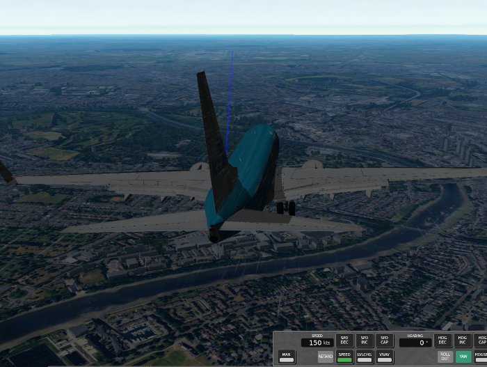
The jet reached 300 feet above ground with a wind at 25 knots from 347 degrees. The runway heading is approximately 270 degrees. A bit too low, but that is an issue with the glide slope controller.
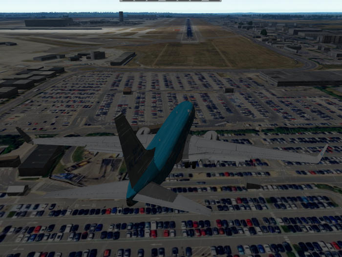
The airplane reached the threshold of runway 27R with wind at 25 knots from 347 degrees. The location of the runway centerline in the simulator is not perfect, which contributes to imperfect alignment with the runway centerline as seen on the satellite imagery.